DIY Princess Mononoke Costume

Last year my wife and I made this Princess Mononoke Costume for our daughter barely in time for Halloween. I just recently noticed I posted to social media but never posted here.

The mask was made with paper mache and paper clay, coated with plasti dip and then painted by MrsRedBeard. The ears, knife and spear were made with foam matting, coated with plasti dip then painted. The fur was a bath mat that MrsRedBeard found, on Amazon I think, which was way cheaper than buying it from a fabric store. The knife handle was made from a ping pong paddle and the spear handle was made from a paint roller handle.

The dress was found at a discount clothing store for very cheap. MrsRedbeard modified the dress, sculpted the necklace with polymer clay and made the fur into something wearable.

The Mask

The Weapons

The finished costume


Microwave Plasma Chamber – Part 3 – What is Plasma? Experiments planned

Photos of plasma being created in a microwave oven from 2 experiments I conducted in the past

Most people are familiar with 3 states of matter being solid, liquid, and gas but a lot of people are not familiar with the 4th. The fourth state of matter is plasma defined as an ionized gaseous mixture consisting of highly charged positive ions and free electrons (negative charge) that result in little or no electric charge. The amount of energy in each state of matter increases as you progress. Plasma is typically created at low pressures or at very high temperatures. Believe it or not plasma is the most common form of matter in the universe. [taken from definition, wiki, and general knowledge]

Examples of plasma are neon signs, CFL bulbs, lightning strikes and probably what I’m most interested in Fusion (the sun). Uses of plasma can be found in the manufacturing of electronic components such as semiconductors, metal plating of glass/silicon/etc, mineral extraction, ion propulsion and one day a very clean and efficient energy source.

Plasma conducts electricity and can be manipulated with a magnetic field. These properties are at the core of what I want to accomplish with the plasma chamber.

Experiments for the chamber

  • Small scale plasma accelerator
  • Plasma sputter plating of metals on to glass
  • Ion drive simulation
  • Magnetic containment fields
  • Effect of plasma being pushed through a coil
  • Plasma being formed with various gases and/or particle filled gases
  • Custom waveguide antennas to concentrate energy for various applications
  • Effect of electricity being applied across plasma
  • Effect of shooting electrons through plasma
  • Find a way to manipulate power and frequency of RF signal


Microwave Plasma Chamber Part 1 & Part 2

Click here to browse through posts written about my interests in Microwave Projects

Microwave Plasma Chamber – Part 2 – RF Energy Shielding Primer

RF Shielding Primer

There’s a lot of in-depth overview random basic RF information. With that said I don’t mind getting into the details because this information will help keep me safe while I perform experiments in the future.

Magnetron
Magnetron

A magnetron generates large amounts of RF energy and emits that energy as an antenna pumped through a wave guide. Most microwaves transmit/operate at 2.45GHz. Unless something is wrong with your microwave or you have taken it apart like I will be doing the RF energy, 2.45GHz, transmission is contained within your microwave using a Faraday cage. On your right is an example of a crude Faraday cage. While crude this mesh size would probably be safe to use for 2.4GHz.

Photo from www.physics.montana.edu
Radio in a Faraday Cage photo from http://www.physics.montana.edu/demonstrations/video/5_electricityandmagnetism/demos/radioinfaradaycage.html

A microwave oven works by pumping a lot of RF energy into an enclosure where it bombards the molecules of food or whatever you have put in your microwave. This RF energy is not in a straight line but is guided through a wave guide then and then bounced off the metal walls of the inside of the microwave. The RF energy then vibrates the molecules which creates heat. This is like when you rub your hands together (friction) and they get warm but on a molecular level. What I don’t want is my molecules to get vibrated.

The Faraday cage is made up of the mesh in the window as well as the metal case which share a chassis ground. The mesh in the window blocks the the RF because the mesh size is smaller than the wavelength of 2.45GHz/2450MHz/2450000000Hz. If the mesh size is lower than the nominal wavelength the mesh should be effective. Look at the list below to see what the wavelengths in size is. For this project I plan on using the RF blocking glass that I obtained samples of from Viracon which is way different than a Faraday cage but same principle. You can see the article I linked to but I also included an image here.

  • Full Wavelength = 12.23643cm/122.3643mm = 0.1223643m
  • Half Wavelength = 6.118215cm/61.18215mm
  • Quarter Wavelength = 3.0591cm/30.591075mm

You can calculate the wavelength using the formula ? = c/? or 0.1223640816326531 = 299792000/2450000000

? = frequency in hz, = speed of light in mps 299792000, = Wavelength in meters

N5JLC is my math right?

So basically if my mesh is smaller than 30mm, if I’m right, I should be protected. I plan to use the glass but if needed I will use hardware cloth.

RF Meters

In order to protect myself and nearby electronics I want to monitor external and internal RF to ensure there is not leakage. RF Meters in general are not that difficult to build but ones that cover the 2.4GHz range require a bit more than a germanium diode and multimeter. In short you’ll probably see a 2.4GHz RF Meter project coming soon. Below are some RF Meter projects but if you know of any please let me know.

Frequency Spectrum Chart

Frequency Spectrum

Symbols and Values

  • ? = frequency in hz
  • c = speed of light in meters per second (mps) 299792000
  • ? = Wavelength in meters

Microwave Plasma Chamber – Part 1 – The Plan


Microwave Plasma Chamber – Part 1 – The Plan

Normally I throw together a project with rough notes, research along the way, then after half attempts/failures I get around to cooking that down to a post on here. This time you will get everything. With this project I will be posting my ideas, planning, results of research and the project in stages. Here’s my initial idea written out and some really rough ideas thrown on paper. This has been a project I’ve been wanting to do for some time now and have been talking about it forever.

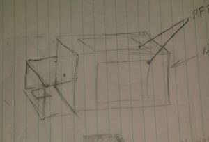
Roughed together a drawing of my ideas and what I think will work for this project. No measurements in mind while throwing ideas on paper.

What I want is a chamber with viewing windows to see the plasma when it’s created. In addition to the view windows and enclosure I will need a power supply to drive this thing.


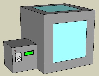
Took my drawing and opened SketchUp with considerations for what measurements I do have. As I type this staring at my digital drawing already considering separating the power supply making it usable for other projects in the future. It would be cool to have a high voltage isolation transformer for things like a Jacobs Ladder or an arc furnace.

Regardless of the power supply what I have in mind here is the plasma chamber with viewing windows which are 12 inches square. I plan to have a microcontroller monitor and remotely turn on or more importantly off the chamber.


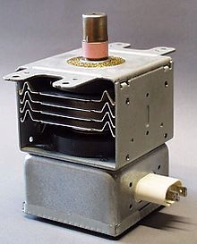
The main chamber will have the magnetron from a microwave mounted inside of it with a metal housing around it and it’s electronics to protect them. The antenna portion of the magnetron will rest inside a waveguide (horn) that points at the center of the chamber. This directed energy will excite particles creating plasma. I probably need to consider a way to draw a vacuum inside the chamber for later experiments.

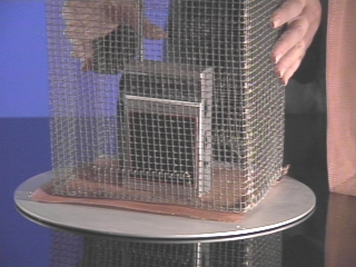
I plan to use parts of the original microwave casing and sheet metal for the housing. If I need more material I might scrap old PC cases. To help minimize RF leakage I am considering using aluminum duct tape and angled aluminum.

Magnetron Wiring

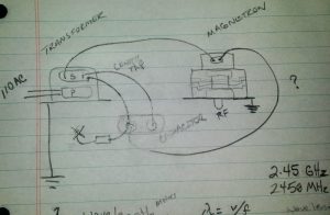
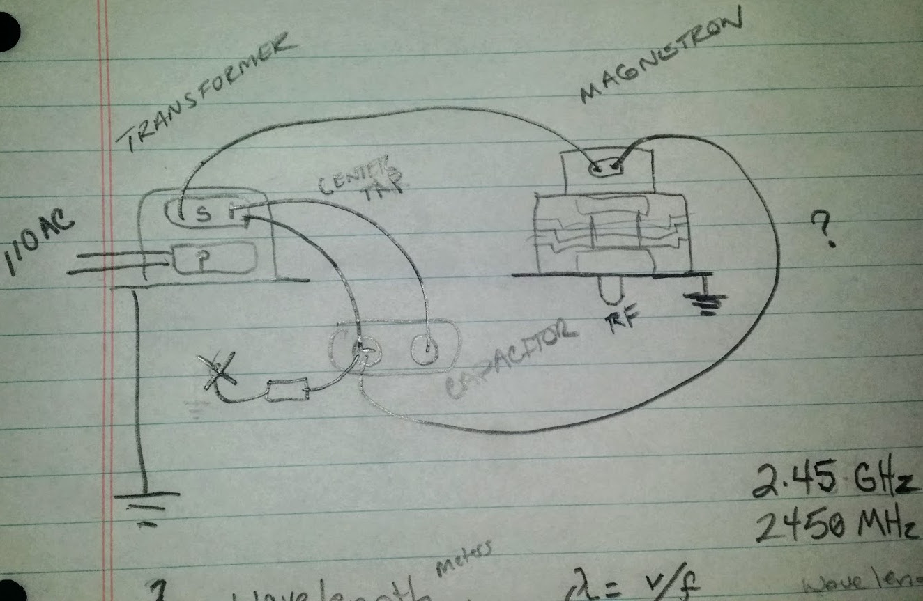
Need to look at the manufacturer specifications and double check my work but I think this how the magnetron wiring is done minus the existing controls.

PreRelease Late Night EditRemember how I said I’d share everything? Well do you see where on the capacitor I have an element leading to an X? I think I already screwed up and that is supposed to be a diode going to chassis ground. 

I also have this crazy idea in the back of my head thinking of using pulse width modulation to have greater control of the RF output. That may be total non-sense but the implications could maybe be cool.

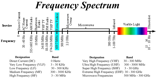
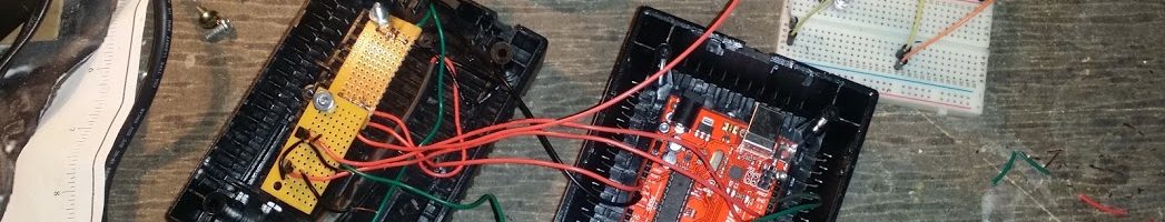
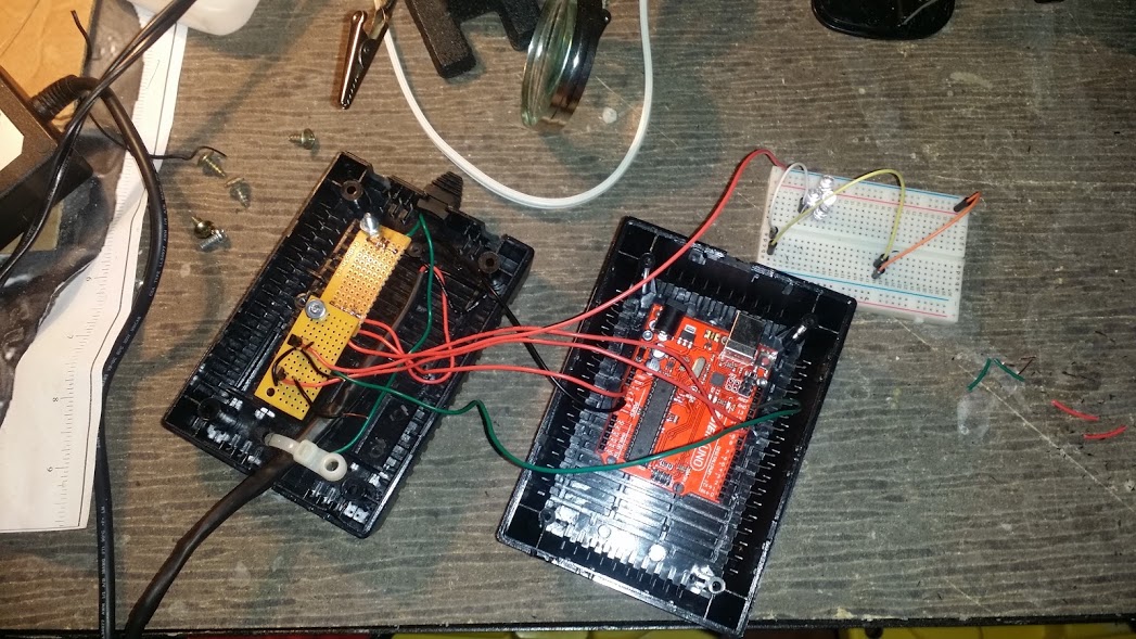
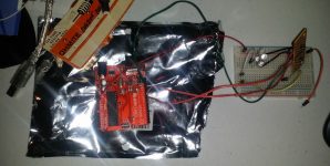
RF meters will be needed to monitor interior and exterior RF levels. I plan to build at least 2 of them and will post that project soon. I will post more about the RF energy in my next post of this project.

Click here to browse through posts written about my interests in Microwave Projects

SainSmart L293D Fail!!

This is a project in the works but what the hey here’s sort of a preview. The plan is to use 2x 400MHz transceivers via 2x arduinos to control the motors on this RC car. I’ve already taken the original controller board out of the car and made room for the new components.

So I was sitting here setting up a SainSmart L293D Motor Driver using specs and guidance from Adafruit and either I missed something or the information is wrong. At 3.5vdc it works but could be pushed so I grabbed an 18vdc drill battery thinking it would be fine because the circuit as quoted from Adafruit below states that it is rated to 25vdc.

25vdc my foot cause as soon as I set it up smoke popped and I smell burning on both the arduino and motor controller. It still seems to work but surely problems will rear their head.

Just ordered better motor controllers (same as the one used in my R2D2) and 18650 battery holders. Wouldn’t be so bad but I think the arduino board is fried.

Just so anyone else is aware this is the link I purchased my L293D from on Amazon. I already complained but I’m not the first to do so.

4 H-Bridges: L293D chipset provides 0.6A per bridge (1.2A peak) with thermal shutdown protection, 4.5V to 25V

https://learn.adafruit.com/adafruit-motor-shield/overview

Arduino and UV Lights for Glow in the Dark Decorations

My wife, MrsRedBeard, made some glow in the dark heads for Halloween decorations. They glowed but very dim and not for very long so why not kick it it up with UV lights. But why stop there when there’s an Arduino laying around?

Using the Arduino I made it so that the lights fade in to brightness, blink, hold for a few seconds then turn off for a while and loop.  The code for this can be found on GitHub.

I’m not getting real in-depth on how to do this because most of it is really basic. If you want additional information just Contact us.

Parts / Materials

  • Arduino
  • UV LEDs from Adafruit
  • An old CAT 5 cable
  • 2 screw terminals
  • 2x 2N3904 Transistors
  • Wire
  • A salvaged project box
  • Styrofoam ring cut in half
  • A empty circuit board

Pictures of the project

DIY DeadMau5 Head on a Budget

Here’s a brief run down on a DIY DeadMau5 head or helmet that I built with my son for Halloween.

Materials

Estimated Cost $33.48

Tools

Cut the half circles to give room for the neck. Magnets hold the spheres together. Put the half spheres together and mark evenly spaced marks around on both spheres to recess 2 sets of magnets total into each side. Don’t do like me and try and use E6000 cause it melts styrofoam, use hot glue just don’t let it get real hot.

Next for the mouth and ears. Use the paper DeadMau5 Mouth template, cut slits into the paper to get the templates to lay evenly and flat onto the surface of the sphere and tape it. Mark lines lightly with a pencil then cut using the hot knife in a well ventilated area. Be careful because the foam melts easy. Use the paper DeadMau5 Ear template to mark and cut the foam for the ears. Note that you will have to cut a curve into the base of the ears to get it to lay flush.

Now for the eyes. Take the 2 Dollar Store Touch Lights apart. You are wanting the dome that acts as a light diffuser. If you get lucky you might be able to use the leds. There will be lip around the outside edge of the dome that will need to be cut off and we used a hot knife for this.

Trace where the ears will be mounted on the sphere then cut/push a recess. Use black hot glue to fix the ears to the sphere. Paint the sphere and ears using acrylic paint. We applied 2 coats to get a good black color applied. Now take the domes you cut out and trace where you want the eyes. Cut/push in the outlines to better recess the domes. In the center of these eye traces you will want to make holes just smaller than the LED you acquired. Hot glue with black glue sticks the eyes. Make Xs on the eyes using electrical tape. Trace the mouth onto the fabric using the DeadMau5 Mouth template tracing slightly larger than the original. Using the black hot glue attach the fabric inside the mouth.

Now it’s time to wire up the LEDs for the eyes. This is pretty simple so I’m not going to post additional info unless asked. Amazon failed to deliver the Red El Wire on time for Halloween but we plan to add that soon. The Red El Wire will outline the ears and mouth.

DIY 100 Watt Bluetooth Speaker

There’s a trend of bluetooth speakers built into suitcases, ammo cans and other unconventional containers. These things sell for $300 or more which is quite a bit more than what it costs to build them. I will break down the parts, sources and their prices. This project was very easy and very affordable.

If you want a custom speaker built just contact us!

Parts

Total cost for one $38.87 (only used one of the speakers)

I found this train case on the side of the road. I stripped out the interior of the case and cleaned it up.


I used a template I found online for the Planet Audio TQ573 5×7 speaker to cut out the hole.

The amp is rated at 50 watts per channel and the speaker is rated at 100 watts. This build only uses one speaker so I bridged the amp to output 100 watts. This amp will run off 12vdc so a portable version would be an easy build.

Speaker mounted and working. It can get pretty loud and sounds great.


RedBeard’s Donnie Darko Mask

Favorite moment of the Donnie Darko mask

I’ve been wanting to make a Donnie Darko Frank the Bunny mask for some time now and finally got around to doing before this last Halloween. Disclaimer I’m no sculptor and have no experience with this. Definitely not perfect and I’m going to retry for something better later but I’ll share anyways.


This was a ton of fun to do but I think I might take some art classes at the AR Innovation Hub, a local maker space, soon.

Materials

I used a combination of paper mache and paper mache clay to make this mask. Paper mache clay is awesome!! I started with a styrofoam form and a blank plastic mask (that was too small).

Cara Brookins has a write up on paper mache clay. Cara is an author and super mom who I hope to interview after reading a few more of her books. I had the pleasure of meeting Cara a few years ago at River City Comic Con.

Errors

As you browse through the progress you’ll notice I started off with an uneven form and it never got better. I thought I’d fill in the lower jaw area to make the mask fill the outline of the printed mask but then removed it with haste. I also found out late that the paper mache clay needs to be kneaded and worked for a while before it becomes pliable. The mask ended up being a bit small but weighed a ton like hurt your neck ton.

I learned a lot from this project. I’m open to any tips you might have for the paper mache clay and sculpting in general.


Mask from the movie no comparison


Pictures from the build


Top